Oscilloscope Probe Setup
-
Attach the probe connector to the appropriate oscilloscope channel.
-
Connect the probe to the appropriate DPT Test Module.
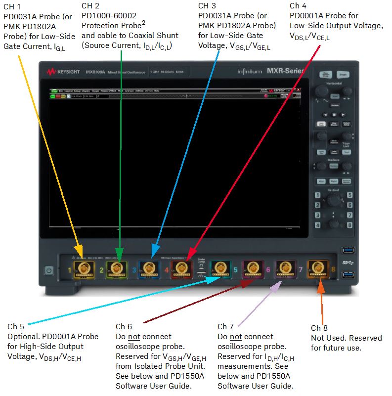
| Oscilloscope Channel | Color | Measures | Oscilloscope Probe |
|---|---|---|---|
| 1 | Yellow | Low-Side Gate Voltage: VGS,L/VGE,L (LOW-SIDE VGS/VCE on Interface Module) |
DP0031A Differential Probe1 (requires banana to BNC adapter) |
| 2 | Green | Low-Side Output Current: ID,L / IC,L (LOW-SIDE ID/IC on Interface Module)2 |
PD1000-60002 Protection Probe and cable to Coaxial Shunt3 |
| 3 | Blue | Low-Side Output Voltage: VDS,L / VCE,L (LOW-SIDE VDS/VCE on Interface Module) |
DP0031A Differential Probe1 (requires banana to BNC adapter) |
| 4 | Red | Low-Side Gate Current, IG,L (IG on Interface Module) | DP0001A High Voltage Differential Probe |
| 5 | Lt Blue | Optional. High-Side Output Voltage,VDS,H / VCE,H (Interface Module HIGH_SIDE VDS/VCE) |
DP0001A High Voltage Differential Probe |
| 6 | Dark Red | Do not connect oscilloscope probe. See “Connect Probe for High-Side DUT Measurements” below and PD1550A Software User Guide. | Reserved for VGS,H/VGE,H from Isolated Probe Unit. |
| 7 | Purple | Do not connect oscilloscope probe. See “Connect Probe for High-Side DUT Measurements” below and PD1550A Software User Guide. | Reserved for ID,H/IC,H. See below and PD1550A Software USer Guide. |
| 8 | Orange | Not used. Reserved for future use. | Not used. Reserved for future use. |
1. Your system may have been provided with PMK PD1802A Differential Probes instead of the Keysight DP0031 probes. These probes are identical in performance.
2. Replace this cable with only the same Keysight part number. The length and type of this cable is assumed for correct Deskew.
3. Use the 0.56 N-m (5 lb-in) 5/16 in. SMA Break-over torque wrench (provided with the PD1550A system) to tighten the SMA cable connector to the PD1000-60002 Protection Probe. Failure
to do so might cause extensive ringing in the DPT measurements. See appendix for details.
-- The maximum input voltage for 50 W input impedance is ±5 V.
-- The maximum input voltage for 1 MW input impedance setting is 30 Vrms or ±40 Vmax (DC + Vpeak).
-- Probing technology allows for testing of higher voltages. No transient over voltage allowed.
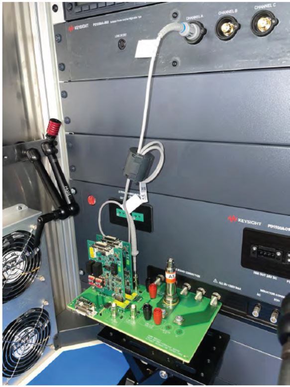
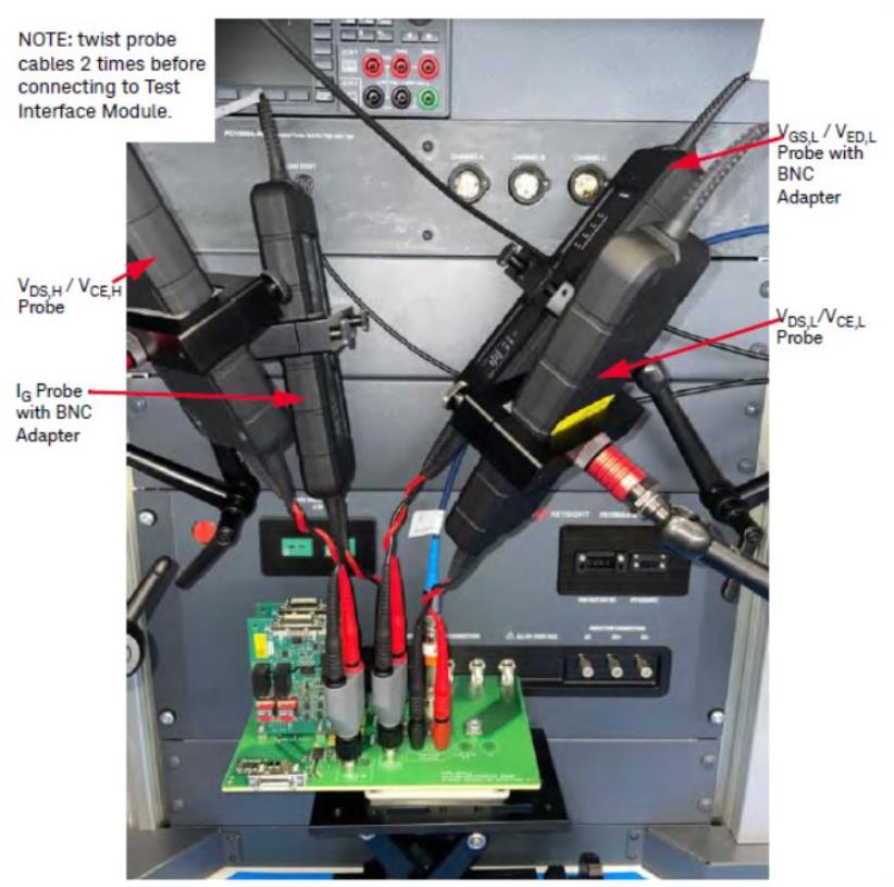
Connect Oscilloscope Probes to DUT Interface Module
Oscilloscope probes connect to the Test Interface Module as follows:

Connect Probes for High-Side DUT Measurements
High-Side Gate Voltage
Keysight’s Isolated Probe Unit is used for High-Side Gate Voltage, VGS,H / VGE,H, measurements only. Only Channel A is used at this time, the remaining channels are reserved for future use. A standard 10:1 oscilloscope probe connects the Channel 1 to the Keysight Interface Module.
Make certain that both Gate Voltage VGS,H/VCE,H and Use Isolated Probe Unit for VGS,H/VCE,H are selected in the Settings > Hardware Configuration > Oscilloscope tab are checked. Default condition is that these two are not checked.
High-Side Drain/Collector Current
For High-Side Drain or Collector current, ID,H/IC,H, measurements, a current shunt is not available for the Keysight 62 mm Interface Modules. However, for your custom Interface Modules you may design a place to install a small Rogowski coil current probe. This should be connected to Channel 7 on the PD1550A oscilloscope.
Make certain that Output Current ID,H/IC,H is selected in the Settings > Hardware Configuration > Oscilloscope tab are checked. Default condition is that this is not checked.